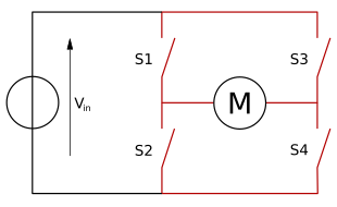
H-bridge
A H-bridge is an electronic circuit that switches the polarity of a voltage applied to a load. These circuits are often used in robotics and other applications to allow DC motors to run forwards or backwards.[1] The name is derived from its common schematic diagram representation, with four switching elements configured as the branches of a letter "H" and the load connected as the cross-bar.
Most DC-to-AC converters (power inverters), most AC/AC converters, the DC-to-DC push–pull converter, isolated DC-to-DC converter[2]most motor controllers, and many other kinds of power electronics use H bridges. In particular, a bipolar stepper motor is almost always driven by a motor controller containing two H bridges.
The term H-bridge is derived from the typical graphical representation of such a circuit. An H-bridge is built with four switches (solid-state or mechanical). When the switches S1 and S4 (according to the first figure) are closed (and S2 and S3 are open) a positive voltage is applied across the motor. By opening S1 and S4 switches and closing S2 and S3 switches, this voltage is reversed, allowing reverse operation of the motor.
Using the nomenclature above, the switches S1 and S2 should never be closed at the same time, as this would cause a short circuit on the input voltage source. The same applies to the switches S3 and S4. This condition is known as shoot-through.
H bridge is used to supply power to a two terminal device. By proper arrangement of the switches, the polarity of the power to the device can be changed. Two example discussed below, DC motor Driver and transformer of switching regulator. Note that, not all of the case of switching condition is safe. The "short"(see below in "DC motor driver" section) cases are dangerous to the power source and to the switches.
Changing the polarity of the power supply to DC motor is used to change the direction of rotation. Apart from changing the rotation direction, the H-bridge can provide additional operation mode, "brake" and "free run until frictional stop". The H-bridge arrangement is generally used to reverse the polarity/direction of the motor, but can also be used to 'brake' the motor, where the motor comes to a sudden stop, as the motor's terminals are shorted. In shorted case, the kinetic energy of a rotating motor consumed rapidly in form of electrical current in the shorted circuit. The other case, to let the motor 'free run' to a stop, as the motor is effectively disconnected from the circuit. The following table summarizes operation, with S1-S4 corresponding to the diagram above. In the table below, "1"is used to represent "on" state of the switch, "0" to represent the "off" state.


