В этой статье отсутствует информация об истории предмета. ( Июнь 2014 г. ) |
Детектор пламени является датчик предназначен для обнаружения и реагировать на присутствие пламени или огня , позволяя обнаружение пламени . Реакция на обнаруженное пламя зависит от установки, но может включать подачу сигнала тревоги, отключение топливопровода (например, пропана или природного газа).линия) и активация системы пожаротушения. При использовании в таких приложениях, как промышленные печи, их роль заключается в обеспечении подтверждения того, что печь работает должным образом; его можно использовать для выключения системы зажигания, хотя во многих случаях они не предпринимают никаких прямых действий, кроме уведомления оператора или системы управления. Детектор пламени часто может реагировать быстрее и точнее, чем детектор дыма или тепла, из-за механизмов, которые он использует для обнаружения пламени. [1] [2]
Оптические датчики пламени [ править ]
Ультрафиолетовый детектор [ править ]
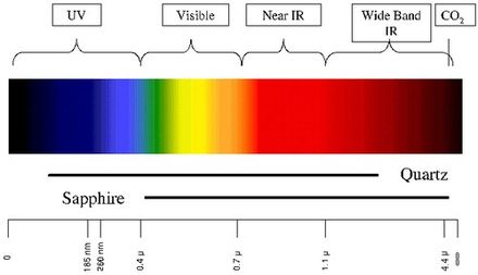
Детекторы ультрафиолета (УФ) работают, обнаруживая УФ-излучение, испускаемое в момент воспламенения. Несмотря на возможность обнаружения пожаров и взрывов в течение 3–4 миллисекунд, временная задержка в 2–3 секунды часто включается для минимизации ложных срабатываний, которые могут быть вызваны другими источниками ультрафиолетового излучения, такими как молния , дуговая сварка , излучение и солнечный свет . УФ-детекторы обычно работают с длинами волн короче 300 нм, чтобы минимизировать влияние естественного фонового излучения . Полоса длин волн УФ-излучения, не пропускающего солнечные лучи, также легко закрывается масляными загрязнениями.
Ближний ИК-массив [ править ]
Вблизи инфракрасные (ИК) датчики пламени массива ( от 0,7 до 1,1 мкм), также известный как детекторы визуального пламени, использует технологию распознавания пламени , чтобы подтвердить огнь анализа ближнего ИК - излучения с использованием прибора с зарядовой связью (CCD). Датчик ближнего инфракрасного диапазона (ИК) особенно способен отслеживать явления пламени без особых препятствий со стороны воды и водяного пара. Пироэлектрические датчики, работающие на этой длине волны, могут быть относительно дешевыми. Несколько каналов или пикселей датчика массива контроля пламени в ближней ИК - диапазоне, возможно, наиболее надежные технологии , доступные для обнаружения пожаров. Световое излучение от огня формирует изображение пламени в определенный момент. Цифровая обработка изображенийможет использоваться для распознавания пламени посредством анализа видео, созданного на основе изображений в ближнем ИК-диапазоне.
Инфракрасный [ править ]
Инфракрасные (ИК) или широкополосные инфракрасные (1,1 мкм и выше) детекторы пламени контролируют инфракрасный спектральный диапазон на предмет определенных рисунков, испускаемых горячими газами. Их обнаруживают с помощью специализированной пожарной тепловизионной камеры (TIC), типа термографической камеры . Ложные тревоги могут быть вызваны другими горячими поверхностями и фоновым тепловым излучением в зоне. Попадание воды на линзу детектора значительно снижает точность детектора, равно как и воздействие прямых солнечных лучей. Специальный частотный диапазон составляет от 4,3 до 4,4 мкм. Это резонансная частота CO 2 . Во время сжигания углеводорода (например, древесины или ископаемого топлива, такого как нефть и природный газ) выделяется много тепла и CO 2.выпущен. Горячий CO 2 излучает много энергии на своей резонансной частоте 4,3 мкм. Это вызывает пик в общем излучении и может быть хорошо обнаружен. Более того, «холодный» CO 2 в воздухе заботится о том, чтобы солнечный свет и другое инфракрасное излучение было отфильтровано. Это делает датчик на этой частоте «солнечным слепым»; однако чувствительность снижается под действием солнечного света. Наблюдая за частотой мерцания огня (от 1 до 20 Гц), извещатель становится менее чувствительным к ложным тревогам, вызванным тепловым излучением, например, вызванным горячим оборудованием.
Серьезным недостатком является то, что почти все излучение может поглощаться водой или водяным паром ; это особенно актуально для инфракрасного обнаружения пламени в диапазоне от 4,3 до 4,4 мкм. Прибл. 3,5 мкм и выше поглощение водой или льдом практически 100%. Это делает инфракрасные датчики для использования вне помещений очень невосприимчивыми к пожарам. Самая большая проблема - это наше невежество; Некоторые инфракрасные детекторы имеют (автоматическую) самопроверку окна детектора, но эта самопроверка отслеживает только появление воды или льда на окне детектора.
Соляная пленка также вредна, потому что соль впитывает воду. Однако водяной пар, туман или небольшой дождь также делают датчик почти слепым без ведома пользователя. Причина аналогична тому, что делает пожарный, приближаясь к горячему огню: он защищает себя с помощью экрана водяного пара от огромного инфракрасного теплового излучения. Присутствие водяного пара, тумана или небольшого дождя также «защищает» монитор, заставляя его не видеть огонь. Однако видимый свет будет проходить через экран из водяного пара, что легко увидеть по тому факту, что человек все еще может видеть пламя через экран из водяного пара.
Обычное время отклика ИК-детектора составляет 3-5 секунд.
Инфракрасные тепловизоры [ править ]
Инфракрасные (IR) камеры MWIR могут использоваться для обнаружения тепла и с помощью определенных алгоритмов могут обнаруживать горячие точки в пределах сцены, а также пламя для обнаружения и предотвращения пожара и рисков пожара. Эти камеры можно использовать в полной темноте и работать как внутри, так и снаружи.
УФ / ИК [ править ]
Эти детекторы чувствительны к длинам волн УФ и ИК и обнаруживают пламя путем сравнения порогового сигнала обоих диапазонов. Это помогает свести к минимуму ложные срабатывания.
ИК / ИК обнаружение пламени [ править ]
Двойные инфракрасные (ИК / ИК) датчики пламени сравнивают пороговый сигнал в двух инфракрасных диапазонах. Часто один датчик смотрит на углекислый газ (CO2) размером 4,4 микрометра, а другой датчик смотрит на опорную частоту. Измерение выбросов CO2 подходит для углеводородного топлива; для топлива на неуглеродной основе, например водорода, обнаруживаются широкополосные водные полосы.
Обнаружение пламени IR3 [ править ]
Мульти-инфракрасные детекторы используют алгоритмы для подавления эффектов фонового излучения (излучения абсолютно черного тела), при этом чувствительность снова снижается из-за этого излучения.
Детекторы пламени с тройным ИК-диапазоном сравнивают три конкретных диапазона длин волн в ИК-области спектра и их соотношение друг с другом. В этом случае один датчик смотрит на диапазон 4,4 микрометра, в то время как другие датчики смотрят на опорные длины волн как выше, так и ниже 4,4. Это позволяет детектору различать источники инфракрасного излучения, не являющиеся пламенем, и фактическое пламя, которое выделяет горячий CO 2 в процессе горения. В результате дальность обнаружения и устойчивость к ложным срабатываниям могут быть значительно увеличены. Детекторы IR3 могут обнаруживать возгорание бензинового поддона площадью 0,1 м 2 (1 фут 2 ) на расстоянии до 65 м (215 футов) менее чем за 5 секунд. Тройные ИК-детекторы, как и другие типы ИК-детекторов, чувствительны к ослеплению слоем воды на окне детектора.
Большинство ИК-детекторов предназначены для игнорирования постоянного фонового ИК-излучения, которое присутствует во всех средах. Вместо этого они предназначены для обнаружения внезапно изменяющихся или возрастающих источников излучения. При воздействии изменяющегося характера ИК-излучения, отличного от пламени, ИК- и УФ / ИК-детекторы становятся более склонными к ложным срабатываниям, тогда как детекторы IR3 становятся несколько менее чувствительными, но более устойчивыми к ложным срабатываниям.
3IR + УФ обнаружение пламени [ править ]
Multi-Infrared (Multi-IR/3IR) detectors use algorithms to determine the presence of fire and tell them apart from background noise known to as " Black-body Radiation," which in generally reduce the range and accuracy of the detector. Black-body Radiation is constantly present in all environments , but is given off especially strongly by objects at high temperature. this makes high temperature environments, or areas where high temperature material is handled especially challenging for IR only detectors. Thus, one additional UV-C band sensor is sometimes included in flame detectors to add another layer of confirmation, as black body radiation does not impact UV sensors unless the temperature is extremely high, such as the plasma glow from an Arc welding machine.
Multi-wavelength detectors vary in sensor configuration. 1 IR+UV, or UVIR being the most common and low cost. 2 IR + UV being a compromise between cost and False alarm immunity and 3 IR + UV, which combines past 3IR technology with the additional layer of identification from the UV sensor.
Multi-Wavelength or Multi-spectral detectors such as 3IR+UV and UVIR are an improvement over their IR-only detectors counterparts which have been known to either false alarm or lose sensitivity and range in the presence of strong background noise such as direct or reflected light sources or even sun exposure. IR detectors have often relied on Infrared bulk energy growth to as their primary determining factor for fire detection, declaring an alarm when the sensors exceed a given range and ratio. This approach however is prone to trigger from non-fire noise. whether from blackbody radiation, high temperature environments, or simply changes in the ambient lighting. alternatively in another design approach, IR-only detectors may only alarm given perfect conditions and clear signal matches, which results in missing the fire when there is too much noise, such as looking into the sunset.
Modern Flame detectors may also make use of high speed sensors, which allow the capture of the flickering movement of flame, and monitor the pattern and ratios of the spectral output for patterns unique to fire.higher speed sensors allow for not only faster reaction times, but also more data per second, increasing the level of confidence in fire identification, or false alarm rejection.
Visible sensors[edit]
A visible light sensor (for example a camera: 0.4 to 0.7 μm) is able to present an image, which can be understood by a human being. Furthermore, complex image processing analysis can be executed by computers, which can recognize a flame or even smoke. Unfortunately, a camera can be blinded, like a human, by heavy smoke and by fog. It is also possible to mix visible light information (monitor) with UV or infrared information, in order to better discriminate against false alarms or to improve the detection range.[3] The corona camera is an example of this equipment. In this equipment the information of a UV camera mixed with visible image information. It is used for tracing defects in high voltage equipment and fire detection over high distances.
In some detectors, a sensor for visible radiation (light) is added to the design.
Video[edit]
Closed-circuit television or a web camera can be used for visual detection of (wavelengths between 0.4 and 0.7 μm). Smoke or fog can limit the effective range of these, since they operate solely in the visible spectrum.[3][4][5]
Other types[edit]
Ionization current flame detection[edit]
The intense ionization within the body of a flame can be measured by means by the phenomena of Flame Rectification whereby an AC current flows more easily in one direction when a voltage is applied. This current can be used to verify flame presence and quality. Such detectors can be used in large industrial process gas heaters and are connected to the flame control system. They usually act as both flame quality monitors and for flame failure detection. They are also common in a variety of household gas furnaces and boilers.
Problems with boilers failing to stay lit can often be due to dirty flame sensors or to a poor burner surface with which to complete the electrical circuit. A poor flame or one that is lifting off the burner may also interrupt the continuity. [6]
Thermocouple flame detection[edit]
Thermocouples are used extensively for monitoring flame presence in combustion heating systems and gas cookers. A common use in these installations is to cut off the supply of fuel if the flame fails, in order to prevent unburned fuel from accumulating. These sensors measure heat and therefore are commonly used to determine the absence of a flame. This can be used to verify the presence of a Pilot flame.
Applications[edit]
UV/IR flame detectors are used in:
- Hydrogen stations.[7]
- Gas-fueled cookers
- Industrial heating and drying systems
- Domestic heating systems
- Industrial gas turbines
Emission of radiation[edit]
A fire emits radiation, which human eye experiences as the visible yellow red flames and heat. In fact, during a fire, relatively sparsely UV energy and visible light energy is emitted, as compared to the emission of Infrared radiation. A non-hydrocarbon fire, for example, one from hydrogen, does not show a CO2 peak on 4.3 μm because during the burning of hydrogen no CO2 is released. The 4.3 μm CO2 peak in the picture is exaggerated, and is in reality less than 2% of the total energy of the fire. A multi-frequency-detector with sensors for UV, visible light, near IR and/or wideband IR thus have much more "sensor data" to calculate with and therefore are able to detect more types of fires and to detect these types of fires better: hydrogen, methanol, ether or sulphur. It looks like a static picture, but in reality the energy fluctuates, or flickers. This flickering is caused by the fact that the aspirated oxygen and the present combustible are burning and concurrently aspirate new oxygen and new combustible material. These little explosions cause the flickering of the flame.
Sunlight[edit]
The sun emits an enormous amount of energy, which would be harmful to human beings if not for the vapours and gases in the atmosphere, like water (clouds), ozone, and others, through which the sunlight is filtered. In the figure it can clearly be seen that "cold" CO2 filters the solar radiation around 4.3 μm. An Infrared detector which uses this frequency is therefore solar blind. Not all manufacturers of flame detectors use sharp filters for the 4.3 μm radiation and thus still pick up quite an amount of sunlight. These cheap flame detectors are hardly usable for outdoor applications. Between 0.7 μm and approx. 3 μm there is relatively large absorption of sunlight. Hence, this frequency range is used for flame detection by a few flame detector manufacturers (in combination with other sensors like ultraviolet, visible light, or near infrared). The big economical advantage is that detector windows can be made of quartz instead of expensive sapphire. These electro-optical sensor combinations also enable the detection of non-hydrocarbons like hydrogen fires without the risk of false alarms caused by artificial light or electrical welding.
Heat radiation[edit]
Infrared flame detectors suffer from Infrared heat radiation which is not emitted by the possible fire. One could say that the fire can be masked by other heat sources. All objects which have a temperature higher than the absolute minimum temperature (0 kelvins or −273.15 °C) emit energy and at room temperature (300 K) this heat is already a problem for the infrared flame detectors with the highest sensitivity. Sometimes a moving hand is sufficient to trigger an IR flame detector. At 700 K a hot object (black body) starts to emit visible light (glow). Dual- or multi-infrared detectors suppress the effects of heat radiation by means of sensors which detect just off the CO2 peak; for example at 4.1 μm. Here it is necessary that there is a large difference in output between the applied sensors (for example sensor S1 and S2 in the picture). A disadvantage is that the radiation energy of a possible fire must be much bigger than the present background heat radiation. In other words, the flame detector becomes less sensitive. Every multi infrared flame detector is negatively influenced by this effect, regardless how expensive it is.
Cone of vision[edit]
The cone of vision of a flame detector is determined by the shape and size of the window and the housing and the location of the sensor in the housing. For infrared sensors also the lamination of the sensor material plays a part; it limits the cone of vision of the flame detector. A wide cone of vision does not automatically mean that the flame detector is better. For some applications the flame detector needs to be aligned precisely to take care that it does not detect potential background radiation sources. The cone of vision of the flame detector is three dimensional and is not necessarily perfectly round. The horizontal angle of vision and the vertical angle of vision often differ; this is mostly caused by the shape of the housing and by mirroring parts (meant for the self test). Different combustibles can even have a different angle of vision in the same flame detector. Very important is the sensitivity at angles of 45°. Here at least 50% of the maximum sensitivity at the central axis must be achieved. Some flame detectors here achieve 70% or more. In fact these flame detectors have a total horizontal angle of vision of more than 90°, but most of the manufacturers do not mention this. A high sensitivity on the edges of the angle of vision provides advantages for the projection of a flame detector.
The detection range[edit]
The range of a flame detector is highly determined by the mounting location. In fact, when making a projection, one should imagine in what the flame detector "sees". A rule of thumb is, that the mounting height of the flame detector is twice as high as the highest object in the field of view. Also the accessibility of the flame detector must be taken into account, because of maintenance and/or repairs. A rigid light-mast with a pivot point is for this reason recommendable. A "roof" on top of the flame detector (30 x 30 cm, 1 x 1-foot) prevents quick pollution in outdoor applications. Also the shadow effect must be considered. The shadow effect can be minimized by mounting a second flame detector in the opposite of the first detector. A second advantage of this approach is, that the second flame detector is a redundant one, in case the first one is not working or is blinded. In general, when mounting several flame detectors, one should let them "look" to each other not let them look to the walls. Following this procedure blind spots (caused by the shadow effect) can be avoided and a better redundancy can be achieved than if the flame detectors would "look" from the central position into the area to be protected. The range of flame detectors to the 30 x 30 cm, 1 x 1-foot industry standard fire is stated within the manufacturers data sheets and manuals, this range can be affected by the previously stated de-sensitizing effects of sunlight, water, fog, steam and blackbody radiation.
The square law[edit]
If the distance between the flame and the flame detector is large compared to the dimension of the fire then the square law applies: If a flame detector can detect a fire with an area A on a certain distance, then a 4 times bigger flame area is necessary if the distance between the flame detector and the fire is doubled. In short:
Double distance = four times bigger flame area (fire).
This law is equally valid for all optical flame detectors, including video based ones. The maximum sensitivity can be estimated by dividing the maximum flame area A by the square of the distance between the fire and the flame detector: c = A/d2. With this constant c can, for the same flame detector and the same type of fire, the maximum distance or the minimum fire area be calculated: A=cd 2 and d=√A/c
It must be emphasized, however, that the square root in reality is not valid anymore at very high distances. At long distances other parameters are playing a significant part; like the occurrence of water vapour and of cold CO2 in the air. In the case of a very small flame, on the other hand, the decreasing flickering of the flame will play an increasing part.
A more exact relation - valid when the distance between the flame and the flame detector is small - between the radiation density, E, at the detector and the distance, D, between the detector and a flame of effective radius, R, emitting energy density, M, is given by
E = 2πMR2/(R2+D2)
When R<<D then the relation reduces to the (inverse) square law
E = 2πMR2/D2
See also[edit]
- Flame
- Active fire protection
- Flame ionization detector
- Gas detector
- Fire alarm system
References[edit]
- ^ Barrie Jenkins, Peter Mullinger. 2011. Industrial and Process Furnaces: Principles, Design and Operation, Butterworth-Heinemann/IChemE series, p.329. Butterworth-Heinemann. ISBN 0080558062
- ^ S. P. Bag. 1995. Fire Services in India: History, Detection, Protection, Management, Environment, Training and Loss Prevention, p. 49. Mittal Publications. ISBN 8170995981
- ^ a b Chenebert, A.; Breckon, T.P.; Gaszczak, A. (September 2011). "A Non-temporal Texture Driven Approach to Real-time Fire Detection" (PDF). Proc. International Conference on Image Processing: 1781–1784. CiteSeerX 10.1.1.228.875. doi:10.1109/ICIP.2011.6115796. ISBN 978-1-4577-1303-3.
- ^ Töreyin, B. Ugur; Dedeoglu, Yigithan; Cetin, A. Enis (2005). Flame detection in video using hidden Markov models (PDF). IEEE International Conference on Image Processing. 2. pp. 1230–3. doi:10.1109/ICIP.2005.1530284. hdl:11693/27294. ISBN 978-0-7803-9134-5.
- ^ Dunnings, A., Breckon, T.P. (2018). "Experimentally Defined Convolutional Neural Network Architecture Variants for Non-temporal Real-time Fire Detection" (PDF). Proc. International Conference on Image Processing. IEEE. Retrieved 9 August 2018.CS1 maint: multiple names: authors list (link)
- ^ "Why Flame Rod Failures Happen and How to Prevent Them. | HVAC Service Mentor".
- ^ Karner, Don; Francfort, James (December 2003). "Arizona Public Service—Alternative Fuel (Hydrogen) Pilot Plant Design Report". U.S. Department of Energy FreedomCAR & Vehicle Technologies Program: Appendix F (pdf). Cite journal requires
|journal=(help)
| vteFire protection | |||||
|---|---|---|---|---|---|
| General |
| ||||
| Fire suppression |
| ||||
| Detection |
| ||||
| Notification |
| ||||
| Awards |
| ||||
| |||||